API 6A Wellhead Tubing Drilling Spool Wellhead & Well Control Equipment Tubing/Casing Head
Casing hanger API Casing Spool Casing Head
1.Casing head spools are provided with a seat for secondary sealing. The lower flange can be provided with a second smaller supplementary ring gasket allowing the maximum pressure build-off with one stage.
2.The casing spools used to suspend and to seal the casings.
3.The flanges and the passing inside diameters are designed according to API spec.6A.

Specifications and parameters
| Nominal Dimension of Top Flange (in) | 11,13-5/8,20-3/4,21-1/4 |
| Working Pressure of Top Flange (MPsi) | 2,3,5,10 |
| Surface Casing Dimension(in) | 20,13-3/8,9-5/8,7 |
| Nominal Diameter of Side Outlet (in) | 2-1/16,2-9/16,3-1/8 |
1. Casing Head-Bottom Slip Connection
Characteristics:
(1) Connect surface casing by type WD slip.
(2) Adopt type BT secondary seal structure.
(3) Accurately calculate casing string's length is not necessary.
(4) Can not be affected by surrounding environment, climate, etc.
(5) Easy, rapid, safe and reliable in installation.
We can apply to different sizes casing, such as: 30",20",13-3/8",12-1/4",9-5/8",7",5-1/2".
We can apply to different sizes casing as:13-3/8",9-5/8",7",5-1/2"etc.
We can manufacture a variety of bottom thread such as CSG, LCSG, BCSG, TM, for the connection between casing head and surface casing.
2. Casing Head-Bottom thread connection
(1)Bottom of the casing head connects surface casing by various types of threads,such as CSG,LCSG,BCSG,TM,ETC.
(2)Convenience and rapid in installation,safe and reliable in operation.
3. Casing Head-Bottom welded connection
(1)Bottom of the casing head connects surface casing by welding.
(2)There's pressure test hole, which can test welding effect, in welding annular space.
Bottom can be connected to surface casing by the method of sleeve welding.Pressure testing holes are designed for the test of welding effect.
Applied Casing Program:20",13-3/8",9-5/8",7",5-1/2", etc.

The casing head is used to fix the wellhead of the drilling well, connect the downhole casing, and reliably seal and control the annular space between the pipes. It is an important part of the oil (gas) wellhead device in the oil field. The casing head is designed with a 45° shoulder to support the weight of the casing string transmitted by the casing hanger, and the bottom can be sealed with a B T type secondary seal.
General Specifications and parameters
| Working Pressure | 2000Psi - 20000Psi |
| Nominal Diameter | 7.1/16" -21.1/4" |
| Working Medium | petroleum, natural gas, slurry, containing H2S and CO2 |
| Working Temperature | L·U (-46℃~ 121℃) |
| Material Grade | AA BB CC DD EE FF HH |
| Product Specification Level | PSL1~4 |
| Performance Requirement | PR1~3 |
| Or as per customer's requirements |

A casing head forms part of the wellhead of an oil or gas drilling well. This wellhead represents the portion of the well that is visible above the ground, and the casing head sits just at the base of this device. Casing heads rest just atop the main operating components of a well, including the drivepipe or conductor pipe. They are generally fixed in place, along with the rest of the wellhead. The majority of moving components within the well system are located underground below the casing head.
Each casing head consists of a heavy-duty steel flange. It may be constructed from galvanized steel or special alloys to increase corrosion-resistance in the often extreme conditions found on an oil field. This device is welded or bolted to the drivepipe mechanism below to create a stable and permanent bond. Each of these steel flanges must be designed to accommodate extreme levels of pressure and temperature ranges, which are common in oil and gas drilling.
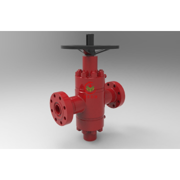
The casing head on a well is primarily used to house a series of blowout preventors (BOP) units. Many wells include two types of BOP units, including both ram and annular models. Blowout preventers are critical to the safety and performance of the well. These specialty valves are equipped to handle extremely high levels of pressure, and are designed to self-adjust to regulate pressure changes. Each of these valves may be bolted or welded to the casing head.

Casing heads also house a variety of surface equipment needed to control and regulate drilling operations. This may include special monitors or panels that measure pressure, temperature, and drilling depth within the well. It also includes pressure-control equipment, including controllers for the blowout preventers and related devices. By serving as a transition point between subsurface and above-ground well components, the casing head often acts as a link between these two areas to hang equipment, wires, and sensors.
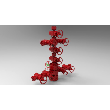
Depending on the application, this casing device may also serve as a base for a specialty assembly of controls and valves used to operate the well. This assembly is often referred to as a Christmas Tree because of its resemblance to a decorated holiday tree, with pipes and valves extending at many different angles. The Christmas tree is used to control the flow of oil or gas to a nearby processing plant, and may also be used to shut off the well when production has halted or ceased.
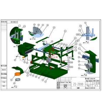
The casing head is connected to the upper end of the casing string and is composed of casing hanger, casing spool and Gate Valve . The casing head is used to support the lower layer of smaller casing string and seal the annular space between the upper and lower layers of casing. The weight of the suspended casing string is borne by the casing hanger.
We are major at Cementing and Fracturing Equipment, Gate Valve and wellhead Christmas Tree,Plunger Pumps and Mud Pumps, Flow line Products, Solid Control Equipment,Drilling Rigs and Work over Rigs Matching Equipment etc.
High quality & Steady quantity & Most competitive price will be sent for you.